
Test the robot when the data stops
A practical ROS 2 fault-injection plan for stale observations, delayed commands and controlled recovery, with an illustrative stopping-distance calculation.
A robot completes its route. The map looks sensible, the controller tracks the path and the demonstration ends where it should. What happens if the next sensor update never arrives?
That is the test I would add before spending another afternoon tuning the happy path. A useful autonomy test should make the information unreliable on purpose, then show what the machine does with the uncertainty.
Give each failure a different test
A silent publisher, a frozen measurement and a delayed callback are different faults. The first stops producing messages. The second can keep producing apparently healthy traffic while repeating an old observation. The third can leave good data waiting while the application is busy.
For a proposed ROS 2 simulation, I would inject these faults separately and retain the original acquisition time, message sequence, receive time and time of use. A timestamp added by a relay should not silently replace the time the sensor actually observed the scene.
| Injected fault | Evidence to inspect |
|---|---|
| Stop the sensor publisher | Time from the last valid observation to the commanded response |
| Replay old observations at the normal rate | Whether acquisition age or sequence checks detect the replay |
| Delay processing under CPU load | Age of the observation when the controller actually uses it |
| Interrupt the command stream | Whether the drive-side timeout produces the specified response |
| Restore data after the fault | Whether motion stays inhibited until the recovery conditions are met |
These are proposed test cases, not results from a robot I have validated. The response and acceptable delay must be specified for the particular machine.
Turn delay into distance
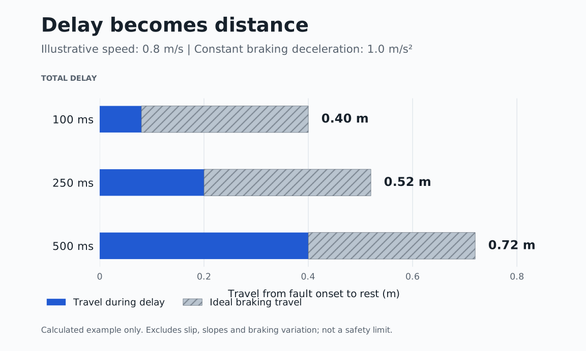
Consider an illustrative mobile robot travelling at 0.8 m/s. Assume it continues at that speed for 0.25 s after a fault, then decelerates uniformly at 1.0 m/s² on a level surface.
During the delay it travels v × t = 0.8 × 0.25 = 0.20 m. The ideal braking distance is v² / (2a) = 0.8² / (2 × 1.0) = 0.32 m. Total travel from fault onset to rest is therefore 0.52 m under these assumptions.
If the total delay grows to 0.50 s, the travel becomes 0.40 + 0.32 = 0.72 m. An extra 250 ms has added 200 mm before the robot stops.
| Assumed total delay | Calculated travel to rest |
|---|---|
| 100 ms | 0.40 m |
| 250 ms | 0.52 m |
| 500 ms | 0.72 m |
The delay budget must include fault detection, scheduling, transport and actuator response without double-counting overlapping stages. This calculation excludes wheel slip, slopes, braking variation, footprint and obstacle motion. It is an illustration of timing consequences, not a protective separation distance or a validated safety limit.
A middleware event is only part of the evidence
The ROS 2 design document for deadline, liveliness and lifespan distinguishes message timing, publisher liveliness and message expiry. Its deadline discussion explicitly places monitoring at the middleware abstraction layer, rather than at completion of the application's work.
That boundary matters when designing a test: a message reaching middleware does not demonstrate that the controller used a fresh observation in time. I would measure the application path as well, and check the actual behaviour of the chosen ROS distribution and middleware implementation.
Use a consistent clock basis when comparing timestamps. In simulation, record whether time is simulated or wall time, and define what a pause or clock reset means for the watchdog. For elapsed-time watchdogs, a clock that can jump needs explicit handling.
Sources: [1]
Trace the command all the way to the drive
Nav2's Humble Collision Monitor documentation describes a node that filters controller velocity commands using sensor-defined zones. Depending on the triggered behaviour, it can reduce or stop the commanded motion. The documentation also states that it does not provide hard real-time safety certification.
For a proposed integration, I would check every command source, including teleoperation and recovery behaviours, against the intended final command path. Then I would verify what the drive does if that path itself stops updating. A zero-velocity message is an instruction; measured motion is the evidence of the response.
Software collision monitoring does not establish the safety rating of the whole machine. Any required safety functions need their own system design and validation. Start fault injection in simulation; physical trials need a controlled test arrangement appropriate to the robot.
Sources: [2]
Make recovery an explicit transition
A returning data stream should not automatically count as permission to move. In a proposed state machine, I would distinguish normal operation, fault response, motion inhibited and ready for a deliberate restart.
Specify what clears the fault: for example, valid observations over a defined interval, acceptable localisation, a healthy command path and a fresh task command. The required checks and any operator acknowledgement depend on the application; a fixed number of good messages is not a universal rule.
Test the awkward sequence too: stop the stream, let a command queue build, restore the connection, then inspect whether old commands are discarded or executed. Include process restarts and clock resets as separate cases.
Keep a fault-to-response record
For each run, retain the software versions, middleware, configuration, injected fault and load conditions. Record fault onset, detection, command change and measured motion on a common timeline. Keep failed runs alongside successful ones.
Before running the experiment, define maximum permitted response time, the required motion state and the conditions for resuming. In simulation, distinguish commanded velocity from simulated physical velocity. On hardware, use suitable independent measurement where the claim requires it.
The useful question at the end is specific: when this input failed under these conditions, did the robot enter the required state within the agreed bound, and did it remain there until recovery was authorised?
Sources and further reading
Sources checked on 23 September 2026. This is a proposed verification approach with illustrative calculations, not a report of completed testing or a safety certification.