
Integrator windup: when a PI loop keeps pushing after the drive has hit its limit
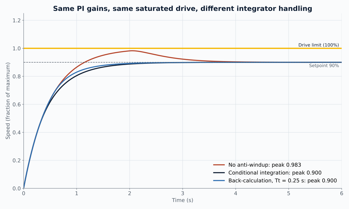
The same PI gains on the same saturated drive overshoot to 98% of full speed without anti-windup and settle at 90% with it. A simulated comparison of no protection, conditional integration and back-calculation.
Every real actuator has a limit. A PWM duty cycle stops at 100%, a valve is fully open, a motor drive clamps its current. A textbook PI controller does not know that.
When the output saturates, the error stays large for longer than the controller expects, and the integral term keeps growing. By the time the process reaches the setpoint, the integrator holds far more than it should, and the loop overshoots while it unwinds.
The simulated loop
The plant is a first-order speed response with a 0.5 s time constant, normalised so 1.0 is full speed. A PI controller with Kp = 2 and Ki = 4 per second drives it, and the drive output is clamped between minus 1 and 1. The setpoint steps from 0 to 0.9.
With these gains the controller asks for well over 100% at the start, so the drive saturates. Everything else is identical between the three runs. Only the integrator handling changes.
| Integrator handling | Peak speed and 2% settling time |
|---|---|
| None | 0.983, 3.1 s |
| Conditional integration (clamping) | 0.900, 1.8 s |
| Back-calculation, Tt = 0.25 s | 0.900, 1.6 s |
The plain PI loop overshoots by 9% and takes almost twice as long to settle, with gains that look perfectly reasonable on paper. On a position axis or a heater, the same mechanism produces larger overshoot because the integral has more time to wind up.
Two standard fixes
Conditional integration stops the integrator accumulating whenever the output is saturated and the error would drive it further into saturation. It is a few lines of code and needs no extra tuning.
Back-calculation feeds the difference between the requested and the actual actuator output back into the integrator through a tracking time constant Tt. When the drive is not saturated the term is zero; when it is, the integrator is pulled back towards a value consistent with what the actuator can actually do. Åström and Murray describe this scheme in their chapter on PID control, with a worked example that removes a large overshoot. [1] Simulink's PID Controller block offers both clamping and back-calculation as built-in options. [2]
In this example both fixes remove the overshoot. Back-calculation settles slightly faster because it keeps the integrator closer to the value it will need at the setpoint.
Things to check on real hardware
The anti-windup logic has to see the real limit. If the firmware clamps duty at 95% for bootstrap reasons but the controller believes the limit is 100%, the integrator still winds up by the difference.
Rate limits count as saturation too. A drive with a ramp limit or a valve with a slew rate holds the output below the request for a while, and the integrator needs to know.
Watch what happens when the loop is switched from manual to automatic, and when a setpoint changes while the output is already at a limit. Both are where windup appears outside a step test. Log the integrator state alongside the output so the cause is visible when it does.
Sources and further reading
Responses are simulated with a 1 ms Euler step using the plant, gains and limit stated in the article. The script and the computed values are linked above.