
A thermistor divider only works across the range it was sized for
Why a 100 kΩ NTC paired with a 100 kΩ resistor leaves the ESP32's suggested ADC range near 106 °C, and how I would size the divider for a hot process.
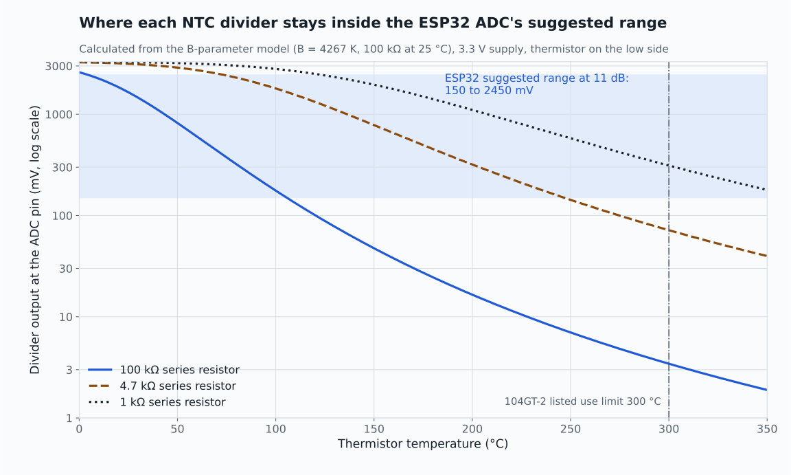
One of my unfinished projects is an ESP32 controller for fusing recycled plastic strips with a heating element. The element could reach about 350 °C, and I never had usable temperature readings from its NTC thermistor. I have not confirmed the cause, so this is not a repair report.
Looking back at the design, the first question I would ask is not about the firmware. It is whether the thermistor circuit could represent the temperatures the heater reaches at all.
A divider matched at 25 °C
A common starting point pairs a 100 kΩ NTC thermistor with a 100 kΩ fixed resistor. From a 3.3 V supply that gives 1.65 V at 25 °C, right in the middle of the range. For a room-temperature sensor it is a sensible choice.
As the thermistor heats, its resistance falls quickly. Using the B-parameter model with B = 4267 K, it is about 5.6 kΩ at 100 °C and about 212 Ω at 250 °C. With the thermistor on the low side of the divider, the output falls to 176 mV at 100 °C and 7 mV at 250 °C.
Espressif's ESP32 documentation lists 150 to 2450 mV as the suggested input range at 11 dB attenuation and states that the most accurate results are obtained within it. This divider leaves that range at about 106 °C.
| Temperature | Calculated output and change per degree |
|---|---|
| 25 °C | 1650 mV, falling 39.5 mV per °C |
| 100 °C | 176 mV, falling 5.0 mV per °C |
| 150 °C | 47 mV, falling 1.1 mV per °C |
| 250 °C | 7 mV, falling 0.11 mV per °C |
A 12-bit converter spanning 2.45 V resolves about 0.6 mV per count. At 250 °C a one-degree change moves this divider by less than a fifth of a count, before any noise is considered.
Sources: [1]
Size the divider for the temperatures that matter
The divider output changes fastest where the thermistor's resistance is close to the fixed resistor. Choosing the fixed resistor near the thermistor's resistance in the control band moves the useful window to where the process operates.
With the same thermistor and supply, a 4.7 kΩ resistor keeps the calculated output inside the suggested range from about 74 °C to about 247 °C. A 1 kΩ resistor moves the window to about 124 °C to 368 °C. At 250 °C the 1 kΩ divider changes by 7.4 mV per °C, compared with 0.11 mV per °C for the 100 kΩ divider.
| Fixed resistor | Calculated temperatures inside 150 to 2450 mV |
|---|---|
| 100 kΩ | About 5 to 106 °C |
| 4.7 kΩ | About 74 to 247 °C |
| 1 kΩ | About 124 to 368 °C |
A calculated window above 300 °C does not extend what the sensor itself is rated for. The rating is covered below.
Account for the current through the thermistor
A smaller fixed resistor passes more current. The power dissipated in the thermistor is greatest when its resistance equals the fixed resistor, where it is V² / (4R). From 3.3 V that is 2.72 mW with a 1 kΩ resistor, at about 167 °C in this model, and 0.58 mW with 4.7 kΩ.
Whether that shifts the reading depends on the thermistor's dissipation constant and how it is mounted and coupled to the heated part. I would check both against the datasheet and the installation rather than assume the effect is negligible. Powering the divider only while sampling is another option worth evaluating.
Check the sensor before the arithmetic
A distributor listing for the widely used ATC Semitec 104GT-2 glass thermistor gives 100 kΩ, a B value of 4267 K, 3% tolerance and suitability for use up to 300 °C. I do not have a record of the exact thermistor fitted to my controller. If it was a part like this, a heater that reaches about 350 °C can take the sensor beyond its listed range.
A single B value is also an approximation away from the temperatures it was characterised at. For a real controller I would use the manufacturer's resistance-temperature data across the operating range and compare readings with a reference thermometer before relying on them.
Sources: [2]
ESP32 details that affect the reading
The same Espressif page notes that the ADC reference voltage varies between chips, from 1000 mV to 1200 mV around the 1100 mV design value, and provides calibration APIs to correct for it. It also describes the ADC as sensitive to noise and suggests a bypass capacitor, such as 100 nF, at the input pad and multisampling.
ADC2 is shared with Wi-Fi, so ADC2 readings can be blocked while Wi-Fi is active. For a connected controller I would put the thermistor on an ADC1 pin.
Sources: [1]
Do not let the reading be the only protection
An open, shorted or detached thermistor can still produce a number. In firmware I would not clamp an out-of-window reading to a plausible temperature. With the thermistor on the low side, a short pulls the output towards 0 V and reads as extreme heat, so a reading below the window should switch the heater off.
The top of the window is harder. With a 4.7 kΩ or 1 kΩ resistor, a healthy sensor at room temperature already reads above 2450 mV, about 3.27 V at 25 °C with 1 kΩ, and an open thermistor reads close to 3.3 V as well. A divider sized for the heat therefore needs a cold-start strategy that can tell a cold sensor from an open one, such as a second divider range or a separate open-circuit check, before the heater is allowed to run under closed-loop control.
My controller also showed why the output side needs the same scrutiny: the element was reported to stay powered while the displayed PWM value was zero. A displayed control output is an instruction, not evidence that the element is off. For a heater that can exceed its sensor's rating, I would want an independent over-temperature cut-out that does not rely on the microcontroller, specified and rated for that element.
Sources and further reading
Sources checked on 26 September 2026. Divider values are calculated from the B-parameter model with B = 4267 K and 100 kΩ at 25 °C. They are not measurements from my controller, and this is not a validated heater design or a completed repair.